
Just as life offers many choices, Java 3D provides many geometry generation options. By reading the relevant section for the geometry option you are interested in using, you can quickly come up to speed on typical usage and learn useful programming tips.
The sections in this chapter describe the mechanics and implementation issues for the geometry generation options available in Java 3D. These are:
The Shape3D classes
(part of the core javax.media.j3d package)
Primitive derived classes (from
com.sun.java.j3d.utils including Box, Cone, Sphere, and so on
Text (2D and 3D) generation
java.lang.Object | +--javax.media.j3d.SceneGraphObject | +--javax.media.j3d.Node | +--javax.media.j3d.Leaf | +--javax.media.j3d.Shape3D
The Shape3D class is essential to defining viewable geometry in Java
3D.
The Shape3D class packages the geometry information for a visual object along with the
appearance information that governs how the geometry is rendered. The Appearance
class is covered in chapter 9 and includes a variety of rendering attributes (material, line, surface attributes, etc.).
In addition, each Shape3D maintains a Bounds object for use in collision detection and intersection testing between PickRays (lines) and other Shape3D
objects in the scene.
As is customary, Shape3D ensures access to internal variables and attributes is subject to the capability
bits that have been set for the Shape3D object.
An example class derived from Shape3D is the ColorCube class. The source code for the ColorCube class is available in the com.sun.java.j3d.utils.geometry
package where ColorCube is defined. The basic principle is to define geometry using one of the
Geometry-derived classes such as QuadArray
and then assign the geometry to the Shape3D using setGeometry(...).
GeometryArray-derived classes can also store the normal vectors, colors, and texture coordinates for
each vertex defined.
A useful feature, defined in Shape3Ds SceneGraphObject base class, is that each
Shape3D has a user data object associated with it. This allows an arbitrary Object-derived
class to be attached to the Shape3D object using:
public void setUserData(java.lang.Object userData);public java.lang.Object getUserData();
The user data object can then be queried in response to scenegraph operations, for example selecting with the mouse. A selection utility
will typically return the Shape3D object that was selected and an application-specific data structure will need to be retrieved to
apply the results of the selection operationthis can be stored in the user data field of the Shape3D object.
The user data field can also be used to remove a scenegraph object once it has been addeda useful function. This technique is described in chapter 5.
java.lang.Object | +--javax.media.j3d.SceneGraphObject | +--javax.media.j3d.Node | +--javax.media.j3d.Group | +--com.sun.j3d.utils.geometry.Primitive
Figure 8.1 Geometric objects derived from Primitive
: sphere, box, cylinder, and cone. Note the different resolution options and how the Primitives are triangulated when drawn as wire framesPrimitive is not part of the Java 3D package (javax.media.j3d)
but has been defined in the Java 3D utilities package (com.sun.java.j3d.utils).
The Primitive class serves as the base class for several simple geometric shapes that can act
as building blocks for Java 3D developers. The Java 3D Primitive-derived
classes have been illustrated in figure 8.1.
Primitive is derived from Groupthat is, it is not a Shape3D object. This is
importanta Primitive is not a shape or geometric object, but is rather a collection of Shape3D
objects. Primitive provides methods to access the subcomponents of the Group.
There is therefore an important distinction between modifying the characteristics of the Primitive (Group
settings) and modifying the properties of the child Shape3D objects (Shape3D settings such as Material,
Appearance, etc.)
Because of serious class design issues regarding the Primitive base class, I cannot recommend that any of the
Primitive-derived classes be used in a Java 3D application of any complexity. The fundamental issue is that the
Primitive class defines a has-a relationship for its geometry. That is, a single
Primitive is defined such that it is a container for its geometric parts. For example,
Box has six geometric parts:
and
To facilitate this relationship the Primitive class is derived from Group.
The Java 3D scenegraph, however, can only have Leaf-derived
geometric objects as leaf nodes, and many operations, such as picking for
mouse-based selection, are performed on Shape3D-derived objects. This lack of compatibility between Shape3D objects and Primitive
objects is something that Sun will address with future releases of Java 3D.
Additionally, it is not generally possible to derive a class from Primitive because the class is not designed to be extensible. For example Primitive.java
contains the following code:
static final int SPHERE = 0x01;static final int CYLINDER = 0x02;static final int CONE = 0x04;static final int BOX = 0x08;This extremely non-object-oriented approach to differentiating between instances of objects derived from Primitive
essentially makes it impossible for application developers to safely create new Primitive-derived
classes. In general, classes at the top of a class hierarchy should not have
knowledge of derived classes.
Example code for all of the Primitive-derived classes is defined in the Sun ConicWorld Java 3D
demo directory. The ConicWorld demo creates a variety of Primitive objects with various lighting, material, and texture attributes.
The following subsections describe the simple geometric Primitives defined in com.sun.j3d.utils.geometry.
java.lang.Object | +--javax.media.j3d.SceneGraphObject | +--javax.media.j3d.Node | +--javax.media.j3d.Group | +--com.sun.j3d.utils.geometry.Primitive | +--com.sun.j3d.utils.geometry.Box
Box defines a simple six-sided cube, illustrated in figure 8.2. Unfortunately for
Swing developers this name conflicts with the Swing class
javax.swing.Box so if your application uses Swing you should reference the Java
3D class explicitly, as in the following:
com.sun.j3d.utils.geometry.Box box =
 new com.sun.j3d.utils.geometry.Box( 0.5f, 0.5f, 0.5f, null);
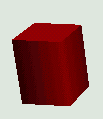
Figure 8.2 The Box Primitive
Box contains the following Shape3Dobjects:
- FRONT = 0;
- BACK = 1;
- RIGHT = 2;
- LEFT = 3;
- TOP = 4;
- BOTTOM = 5;
The identifiers are used as indices into the Primitive Group Node.
In other words, to retrieve the FRONT face of the cube, you must call:
Shape3D frontFace = box.getShape(Box.FRONT );
This is defined in Box.java as:
public Shape3D getShape(int partId)

{

 if (partId < FRONT || partId > BOTTOM)

      return null;

    return (Shape3D)((Group)getChild(0)).getChild(partId);

}
The faces of the Box are Shape3D objects and are children of the first
Node added to the Group. The first Node of the Group
is a TransformGroup object that allows the Box
to be moved as a whole. Thus, modifying the scale, rotation, and translation of
the TransformGroups Transform3D applies the scale, rotation, and translation to all of its child
Nodes also.
The Sun example ConicWorld/BoxExample.java provides an example of creating Boxes
and loading and applying texture images to Boxes.
//Set Appearance attributes

//first, create an appearance

Appearance ap = new Appearance();


//create a colored material

Color3f aColor = new Color3f(0.1f, 0.1f, 0.1f);

Color3f eColor = new Color3f(0.0f, 0.0f, 0.0f);

Color3f dColor = new Color3f(0.8f, 0.8f, 0.8f);

Color3f sColor = new Color3f(1.0f, 1.0f, 1.0f);

Material m = new Material(aColor, eColor, dColor, sColor,
80.0f);


//enable lighting and assign material

m.setLightingEnable(true);

ap.setMaterial(m);


//render the Box as a wire frame

PolygonAttributes polyAttrbutes = new PolygonAttributes();

polyAttrbutes.setPolygonMode( PolygonAttributes.POLYGON_LINE
);

polyAttrbutes.setCullFace(PolygonAttributes.CULL_NONE);

ap.setPolygonAttributes(polyAttrbutes);


//create the box and assign the appearance

Box BoxObj = new Box(1.5f, 1.5f, 0.8f, Box.GENERATE_NORMALS |
Box.GENERATE_TEXTURE_COORDS, ap);


//load and assign a texture image and set texture parameters

TextureLoader tex = new TextureLoader("texture.jpg", "RGB",
this);

if (tex != null)

ap.setTexture(tex.getTexture());

TextureAttributes texAttr = new TextureAttributes();

texAttr.setTextureMode(TextureAttributes.MODULATE);

ap.setTextureAttributes(texAttr);
java.lang.Object


|


+--javax.media.j3d.SceneGraphObject


|


+--javax.media.j3d.Node


|


+--javax.media.j3d.Group


|


+--com.sun.j3d.utils.geometry.Primitive


|


+--com.sun.j3d.utils.geometry.Cone
Cone defines a simple Cone Primitive with a radius and a height, illustrated in figures 8.3 and 8.4. It is a capped cone centered
at the origin with its central axis aligned along the Y-axis. The center of the Cone is defined to be the center of its bounding box (rather than its centroid). If the
GENERATE_TEXTURE_COORDS flag is set, the texture coordinates are generated so that the texture gets
mapped onto the Cone similarly to a Cylinder, except without a top cap.
Cone consists of the following Shape3D objects:
- ALIGN="JUSTIFY">int BODY = 0;
- "JUSTIFY">int CAP = 1;
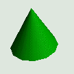
Figure 8.3 The Cone Primitive (low resolution)
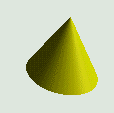
Figure 8.4 The Cone Primitive (high resolution)
By default, 15 surfaces are generated for the sides of the Cone. This can be increased or decreased by using the most customizable constructor:
public Cone(float radius, float height, int primflags,
int xdivision, int ydivision, Appearance ap)
The geometry for the Cone consists of a Cylinder tapering from the supplied radius at one end to zero radius at the other end. A
disk is created using the same number of divisions as the Cylinder and aligned to close the open end of the Cylinder.
8.2.3 Cylinder
java.lang.Object

   |

   +--javax.media.j3d.SceneGraphObject

        |

        +--javax.media.j3d.Node

             |

             +--javax.media.j3d.Group

                  |

                  +--com.sun.j3d.utils.geometry.Primitive

                       |

                       +--com.sun.j3d.utils.geometry.Cylinder
The Cylinder Primitive defines a capped cylinder, illustrated in figure 8.5. Cylinder is composed from three Shape3D
components: Body, Top disk, and Bottom disk.
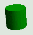
Figure 8.5 The Cylinder Primitive
- int BODY = 0;
- int TOP = 1;
- int BOTTOM = 2;
The default number of surfaces created for the body is 15 along the X-axis and 1
along the Y-axis, the disks are created as 15-sided polygons. Again, use the most complex form of the constructor to vary the number of surfaces
generated for the cylinder:
public Cylinder(float radius, float height, int primflags,

int xdivision, int ydivision, Appearance ap) {
java.lang.Object

  |

  +--javax.media.j3d.SceneGraphObject

       |

       +--javax.media.j3d.Node

            |

            +--javax.media.j3d.Group

                 |

                 +--com.sun.j3d.utils.geometry.Primitive

                      |

                      +--com.sun.j3d.utils.geometry.Sphere
The Sphere Primitive defines a sphere with 15 divisions in both the X- and Y-axes, illustrated in figures 8.6 through 8.8. Use the most customizable form of the constructor to vary the number of surfaces created for the Sphere:
public Sphere(float radius, int primflags, int divisions,

  Appearance ap)
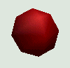
Figure 8.6 The Sphere Primitive (low resolution)
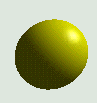
Figure 8.7 The Sphere Primitive (high resolution)

Figure 8.8 Sphere Primitive with an applied texture image of the Earth
All of the Primitives have a primitive flags (primflags) argument in one of their constructors. Primitive flags influence the attributes applied to the Shape3D geometry when it is generated internally for the Primitive. The available primitive flags are shown in table 8.1.
| Primitive flag | Effect |
|---|---|
| ENABLE_APPEARANCE_MODIFY | Set ALLOW_APPEARANCE_READ and ALLOW_APPEARANCE_WRITE capabilities on the generated geometry's Shape3D nodes. |
| ENABLE_GEOMETRY_PICKING | Set ALLOW_INTERSECT capability on the generated geometry. |
| GENERATE_NORMALS | Generate normal vectors along with geometry. |
| GENERATE_NORMALS_INWARD | Normal vectors flipped along the surface. |
| GENERATE_TEXTURE_COORDS | Generate texture coordinates along with geometry. |
| GEOMETRY_NOT_SHARED | Generate geometry that will not be shared by another scene graph node. |
After a Primitive has been generated, the capabilities for the Shape3D subparts can also be accessed by calling
getShape(partid).setCapability(ALLOW_INTERSECT);
Note that the setPrimitiveFlags method should not be used, as it does not have any effect once the Primitive has been created.
Unless primitive flags are explicitly supplied, the default GENERATE_NORMALS primitive flag is used. In other words, both vertex coordinates and normal vectors are generated (to allow surfaces to be lighted).
The Primitive-derived classes use a very simplistic cache to minimize the CPU time used to create the geometry for each class. An analysis of this capability is included in appendix C.
8.3 GeomBuffer
The Primitive-derived classes internally make use of the GeomBuffer helper class. This class allows geometry to be defined using an API similar to OpenGLs stateful display list geometry definition API. This capability is discussed in more detail in appendix C and may be useful for porting OpenGL programs.
java.lang.Object

  |

  +--javax.media.j3d.SceneGraphObject

      |

      +--javax.media.j3d.NodeComponent

           |

           +--javax.media.j3d.Geometry

                |

                +--javax.media.j3d.Raster
The Raster class serves double duty in Java 3D. It can be used to either render an image into the 3D scene at a given location or to read the depth components of the 3D scene. The first application is much more common and easier to describe because it truly represents geometry definition.
A Raster object can be used to simply paste a 2D image into the 3D view.
The Raster has a 3D location associated with it, and this serves as the upper-left corner of the rendered image.
Note however that the image for the Raster is rendered as-is and will not have any scaling, translation, or rotation applied to itregardless of the Rasters position within the scenegraph.
A Raster might be appropriate for graphical coordinate axis labels, for example. Since Raster is derived from Geometry it must be encapsulated by a Shape3D Node before it can be added to the scenegraph.
There are six basic steps to using a Raster:
1. Create the BufferedImage.
2. Read in or generate the image data.
3. Create the ImageComponent2D to wrap the BufferedImage.
4. Create the Raster to wrap the ImageComponent2D.
5. Create the Shape3D to contain the Raster.
6. Add the Shape3D to the scenegraph.
For example:
//create the image to be rendered using a Raster
BufferedImage bufferedImage =
new BufferedImage( 128, 128, BufferedImage.TYPE_INT_RGB);
//load or do something to the image here
//wrap the BufferedImage in an ImageComponent2D
ImageComponent2D imageComponent2D =
new ImageComponent2D( ImageComponent2D.FORMAT_RGB,
bufferedImage);
imageComponent2D.setCapability( ImageComponent.ALLOW_IMAGE_READ );
imageComponent2D.setCapability( ImageComponent.ALLOW_SIZE_READ );
//create the Raster for the image
m_RenderRaster = new Raster( new Point3f( 0.0f, 0.0f, 0.0f ),
Raster.RASTER_COLOR,
0, 0,
bufferedImage.getWidth(),
bufferedImage.getHeight(),
imageComponent2D,
null );
m_RenderRaster.setCapability( Raster.ALLOW_IMAGE_WRITE );
m_RenderRaster.setCapability( Raster.ALLOW_SIZE_READ );
//wrap the Raster in a Shape3D
Shape3D shape = new Shape3D( m_RenderRaster );
The other, more unusual, application for a Raster is to use it to retrieve the depth components of the 3D scene. These are stored in the Z-buffer, a multibyte array that stores the depth into the scene for each rendered pixel. The depth to the first occurrence of geometry is stored in the Z-buffer, and floating point values are scaled such that the closest value to the user is zero while the farthest value is one.
Querying the Z-buffer directly is quite uncommon, but may be useful for such application-specific functionality as hit testing or rendering.
The following example illustrates overriding the Canvas3D postSwap method to retrieve the contents of the Z-buffer for the scene using a Raster object. The Z-buffer Raster is then used to dynamically update an image Raster so that the depth components can be rendered graphically. The output from the RasterTest illustrating this technique is shown in figure 8.9.
Figure 8.9 Two frames from RasterTest. Each frame contains a rotating cube and a Raster displaying the depth components of the entire frame. The Raster is visible because it also has a depth component
| From RasterTest.java |
//size of the window, and hence size of the depth component array
private static int m_kWidth = 300;
private static int m_kHeight = 300;
//the Raster used to store depth components
private Raster m_DepthRaster = null;
//the Raster used to render an image into the 3D view
private Raster m_RenderRaster = null;
//an array of integer values for the depth components
private int[] m_DepthData = null;
//create the image to be rendered using a Raster
BufferedImage bufferedImage = new BufferedImage( 128, 128, BufferedImage.TYPE_INT_RGB );
ImageComponent2D imageComponent2D = new ImageComponent2D( ImageComponent2D.FORMAT_RGB, bufferedImage );
imageComponent2D.setCapability( ImageComponent.ALLOW_IMAGE_READ );
imageComponent2D.setCapability( ImageComponent.ALLOW_SIZE_READ );
//create the depth component to store the 3D depth values
DepthComponentInt depthComponent = new DepthComponentInt( m_kWidth,
m_kHeight );
depthComponent.setCapability( DepthComponent.ALLOW_DATA_READ );
//create the Raster for the image
m_RenderRaster = new Raster( new Point3f( 0.0f, 0.0f, 0.0f ),
Raster.RASTER_COLOR,
0, 0,
bufferedImage.getWidth(),
bufferedImage.getHeight(),
imageComponent2D,
null );
m_RenderRaster.setCapability( Raster.ALLOW_IMAGE_WRITE );
m_RenderRaster.setCapability( Raster.ALLOW_SIZE_READ );
//create the Raster for the depth components
m_DepthRaster = new Raster( new Point3f( 0.0f, 0.0f, 0.0f ),
Raster.RASTER_DEPTH,
0, 0,
m_kWidth,
m_kHeight,
null,
depthComponent );
//create a custom Canvas3D with postSwap overridden
GraphicsConfigTemplate3D gc3D = new GraphicsConfigTemplate3D();
gc3D.setSceneAntialiasing( GraphicsConfigTemplate.PREFERRED );
GraphicsDevice gd[] = GraphicsEnvironment.getLocalGraphicsEnvironment().getScreenDevices();
RasterCanvas3D c3d =
new RasterCanvas3D( this, gd[0].getBestConfiguration( gc3D) );
c3d.setSize( getCanvas3dWidth( c3d ), getCanvas3dHeight( c3d ) );
//create a Shape3D object for the Raster containing the Image
Shape3D shape = new Shape3D( m_RenderRaster );
//add the Rasters Shape3D to the Scenegraph
objRoot.addChild( shape );
//take the Depth Raster and update the Render Raster containing
//the image based on the depth values stored in the Depth Raster.
//create a temporary BufferedImage for the depth components
BufferedImage tempBufferedImage =
new BufferedImage( m_DepthRaster.getDepthComponent().getWidth(),
m_DepthRaster.getDepthComponent().getHeight(),
BufferedImage.TYPE_INT_RGB );
//allocate an array of integers to store the depth components
//from the Depth Raster
m_DepthData =
new int[ m_DepthRaster.getDepthComponent().getWidth() *
m_DepthRaster.getDepthComponent().getHeight () ];
//copy the depth values from the Raster into the integer array
((DepthComponentInt) m_DepthRaster.getDepthComponent()).
getDepthData( m_DepthData);
//assign the depth values to the temporary image. the integer
//depths will be interpreted as integer rgb values.
tempBufferedImage.setRGB(
0, 0,
m_DepthRaster.getDepthComponent().getWidth (),
m_DepthRaster.getDepthComponent().getHeight(),
m_DepthData, 0,
m_DepthRaster.getDepthComponent().getWidth() );
//get a graphics device for the image
Graphics g = tempBufferedImage.getGraphics();
Dimension size = new Dimension();
m_RenderRaster.getSize( size );
//The Depth Raster is a different size than the Render Raster.
//i.e., if the Depth Raster is canvas width by canvas height and
//the Render Raster is of arbitrary size, we rescale the image here.
g.drawImage( tempBufferedImage,
0, 0,
(int) size.getWidth(),
(int) size.getHeight(), null);
//finally, assign the scaled image to the RenderRaster
m_RenderRaster.setImage(
new ImageComponent2D( BufferedImage.TYPE_INT_RGB,
tempBufferedImage) );
//Canvas3D overridden method to read the depth components
// of the 3D view into a Raster object and notify the Applet
class RasterCanvas3D extends Canvas3D
{
RasterTest m_RasterTest = null;
public RasterCanvas3D( RasterTest rasterTest,
GraphicsConfiguration gc)
{
super( gc );
m_RasterTest = rasterTest;
}
public void postSwap()
{
super.postSwap();
getGraphicsContext3D().readRaster(
m_RasterTest.getDepthRaster() );
//notify the applet to update the render object used
//to display the depth values
m_RasterTest.updateRenderRaster();
}
}
![]()
java.lang.Object

  |

  +--javax.media.j3d.SceneGraphObject

       |

       +--javax.media.j3d.Node

            |

            +--javax.media.j3d.Leaf

                 |

                 +--javax.media.j3d.Shape3D

                      |

                      +--com.sun.j3d.utils.geometry.Text2D
Text2D creates a texture-mapped rectangle that displays a text string. The size of the rectangle and its texture map are customizable through the constructor.
The resulting Shape3D object is a transparent (except for the text) rectangle located at 0, 0, 0 and extending up the positive Y-axis and out the positive X-axis.
Text2D essentially creates an image when it is constructed and draws the text string into the image. This texture image is then applied (once) at construction to the rectangular geometry.
| NOTE | The setRectangleScaleFactor/getRectangleScaleFactor methods may appear to have no effect, but note the following Sun bug report: the setRectangleScaleFactor method will not change text size unless the setString method is called.
It must therefore be called before any calls to setString are made. |
|---|
Figure 8.10 Two frames from RasterTest. Each frame contains a rotating cube and a Raster displaying the depth components of the entire frame. The Raster is visible because it also has a depth component
As a Text2D object is merely a rectangle with a texture applied to its front, it is interesting to consider the trade-off between creating the Text2D object with larger font sizes and scaling the Text2D object as a whole. On the one hand, creating a Text2D object with a larger font size will create a larger rectangle, and larger texture image will be applied to the rectangle. Applications require more memory to handle larger texture images, and increased memory requirements could become significant if large numbers of Text2D objects are created with large font sizes. On the other hand, creating a Text2D object with a small font and then scaling the object using a TransformGroup will result in smaller texture images and lower memory requirements, but image resolution will be compromised as the texture image is scaled. These trade-offs are illustrated in figure 8.10.
A more interesting Text2D implementation would have the ability to regenerate its texture image based on the Text2D objects distance from the viewer. In this way the Text2D could automatically incorporate LOD-type behavior, creating high-resolution text string images when viewed up close, and saving memory by dynamically creating low-resolution text string images when viewed from afar.
Also, be aware that because a Text2D object applies the string as a texture image, the texture image is only viewable from the right side of the Text2D object. To use the Text2D object as a label a Billboard type behavior will have to be used to ensure the back face of the Text2D object is never visible to the viewer.
java.lang.Object
  |
  +--javax.media.j3d.SceneGraphObject
        |
        +--javax.media.j3d.NodeComponent
              |
              +--javax.media.j3d.Geometry
                    |
                    +--javax.media.j3d.Text3D
The Text3D class generates 3D geometry for a given font, with a given extrusion, as shown in figure 8.11. In contrast to the Text2D class, which merely generates an image of the text string in a given font, Text3D creates a true complex 3D object that forms the text string supplied. The font and pitch describe the generated geometry in the X and Y dimensions, whereas a FontExtrusion object describes the font in the Z direction.

Although Text3D is relatively straightforward to use, it is often more of a problem, in applications that use Text3D objects as labels, to ensure that the Text3D object is always aligned relative to the viewer so as to be easily visible.
The following example creates a simple 10-point SansSerif 3D-text label and encapsulates it in a Shape3D object.
| From BillboardTest.java (see also Text3DTest.java) |
Font3D f3d = new Font3D( new Font( "SansSerif", Font.PLAIN, 10),
new FontExtrusion () );
Text3D label3D = new Text3D( f3d, Hello World, locationPoint );
Shape3D sh = new Shape3D( label3D );![]()
The names of the available font families (e.g., SansSerif) can be retrieved using
java.awt.GraphicsEnvironment.getAvailableFontFamilyNames
A FontExtrusion object can be used to control the depth of text as follows:
| From Text3DTest.java |
//describe the FontExtrusion contour using X,Y coordinates
//that in mathematical parlance are monotonic in X
double X1 = 0;
double Y1 = 0;
double X2 = 3;
double Y2 = 0;
Shape extrusionShape = new java.awt.geom.Line2D.Double(X1, Y1, X2, Y2);
FontExtrusion fontEx = new FontExtrusion( extrusionShape) ;
Font3D f3d = new Font3D( new Font( "TimesRoman",
Font.PLAIN, nSize),
fontEx);![]()
This example will create a Text3D object that is 3 units deep instead of the default 0.2 units.
Unfortunately, there are serious usability issues that may influence your decision to use a Text3D object. These are described in the following subsections.
Text3D objects can contain many hundreds of vertices. Creating lots of Text3D objects may quickly consume memory and impact performance. The number of vertices created is proportional to the pitch of the font used, as well to the font itself. Using small sans serif fonts will generate fewer vertices than large serif fonts. This is particularly relevant if your application uses the Java 3D collision detection methods; internally Text3D creates a GeometryArray object for each letter. If you create many Text3D objects with many letters, each containing many vertices, collision detection will quickly consume all available processor time.
Text3D objects generate vertex coordinates and Normal vectors for their geometry. This implies that they can be displayed and lighted, but cannot have a texture image applied to them.
There is essentially no way to modify the contents of a Text3D object at runtime, for example, to create dynamic or context sensitive labels. The misleading setString method does not destroy the previously generated geometry within the Text3D object, but appends new geometry to the object (figure 8.12). In addition, it does not honor the font, pitch, and other dimensions that were specified when the Text3D object was created. setString( null ) can be used to not display the Text3D object, though this is probably not useful as there would be no way to restore the object without generating more geometry. Note that setString( "" ) causes a NullPointerException. I expect Sun to address these bugs in the immediate future so check your implementation version.

java.lang.Object
  |
  +--javax.media.j3d.SceneGraphObject
        |
        +--javax.media.j3d.Node
              |
              +--javax.media.j3d.Leaf
                    |
                    +--javax.media.j3d.Morph
The Morph Node is similar to a normal Shape3D Node except that is can have multiple GeometryArray objects associated with it. You can therefore put four versions of the same geometry into a Morph object and progressively morph between them by adjusting the weights associated with each GeometryArray.
Table 8.2 shows the coordinates for the first point from four GeometryArrays, along with the weight for each. First, each coordinate is multiplied by the weight of its GeometryArray, and then the sum of all weighted coordinates is taken as the resulting coordinate.
| GeometryArray | Weight | X | Y | Z | W x X | W x Y | W x Z |
|---|---|---|---|---|---|---|---|
| 1 | 0.5 | 10 | 10 | 0 | 5 | 5 | 0 |
| 2 | 0.25 | 20 | 5 | 0 | 5 | 1.25 | 0 |
| 3 | 0.125 | 5 | 10 | 0 | 0.625 | 1.25 | 0 |
| 4 | 0.125 | 10 | 2 | 0 | 1.25 | 0.25 | 0 |
| Resulting Point | 8.125 | 4.75 | 0 |
Note that the sum of the GeometryArray weights should equal 1.
As you would expect, there has to be a one-to-one correspondence between the points in each GeometryArray. There is no feature information, so Java 3D merely uses the indices of each coordinate in the array to compute the resulting coordinates. In addition, all the GeometryArrays must have the same vertex format, the GeometryArrays must be of the same type, and must have comparable texture coordinate specifications.
Please refer to the Sun Java 3D Morphing example to see the Morph Node in action.
This chapter has introduced a lot of the nitty-gritty details of using the various scenegraph Nodes to define Geometry. At the heart of all these options is the Shape3D Node and the GeometryArray class for containing arrays of vertex coordinates, colors, and texture coordinates. This chapter is intended to augment the official documentation so please refer to your JavaDoc for information on the various APIs.
Now that you know how to create your geometry you are probably wondering how you can control its appearanceboth at creation time, and dynamically at runtime. The next chapter introduces the Appearance class that you associate with a Shape3D instance to do just that.